You can manually enter individual values for tolerance and roughness fields for a specific GCD:
Use the Tolerance Editor
To set tolerance policies, use the Tolerance Policy Editor - see Use the Tolerance Policy Editor
-
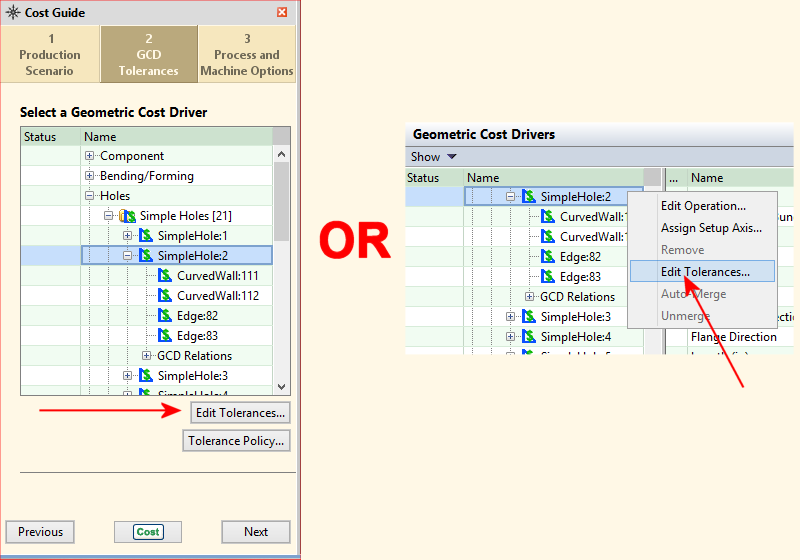
To open the Tolerance Editor, select a GCD, either:
-
From the tab of the Cost Guide, click the Edit Tolerances button.
-
From the Geometric Cost select Edit Tolerances from the right-click context menu.
-
-
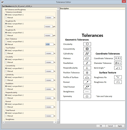
The Tolerance Editor displays, showing a list of tolerances that apply to that type of GCD (as described for the Tolerance Policy Editor - see Use the Tolerance Policy Editor).
-
To set specific tolerance values, select Manual, then enter the value in the associated field.
-
Click OK when done.
Use the Geometric Cost Drivers pane
-
Select the GCD or GCDs to be modified. You can use either the Viewer or the Geometric Cost Drivers pane.
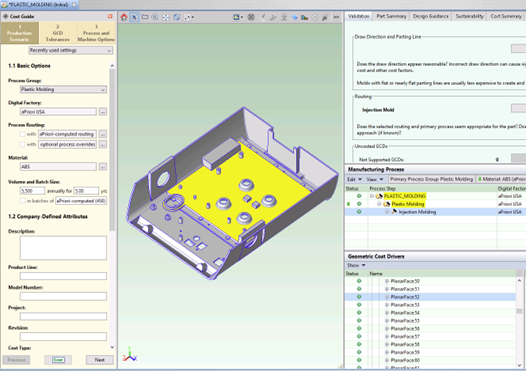
The image below shows that the user has selected a Planar Face GCD in Viewer.
You can select multiple GCDs as long as they are of the same type (such as Planar Face or Curved Wall, and so forth).
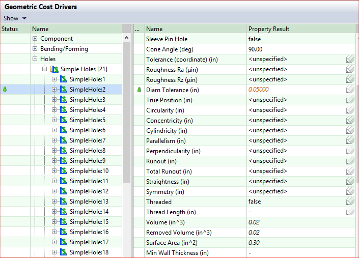
The image below shows that the user has selected a Simple Hole GCD in the Geometric Cost Drivers pane.
Note that
-
The Name column lists the tolerances that apply to this GCD (along with other values) as well as the properties Threaded and Thread Length.
-
The pencil icon indicates fields that can be edited.
-
-
Double-click the field in the Property Result column enter the value you wish to apply.
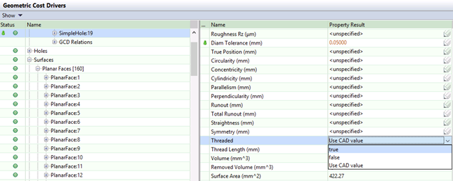
Override values appear in red italic and a green User Override icon appears in the left column.
-
To remove an existing tolerance value, double-click and delete the entered value, or right-click the value and select Return to Auto-Select.
-
Press Enter, Tab, or click on another property.